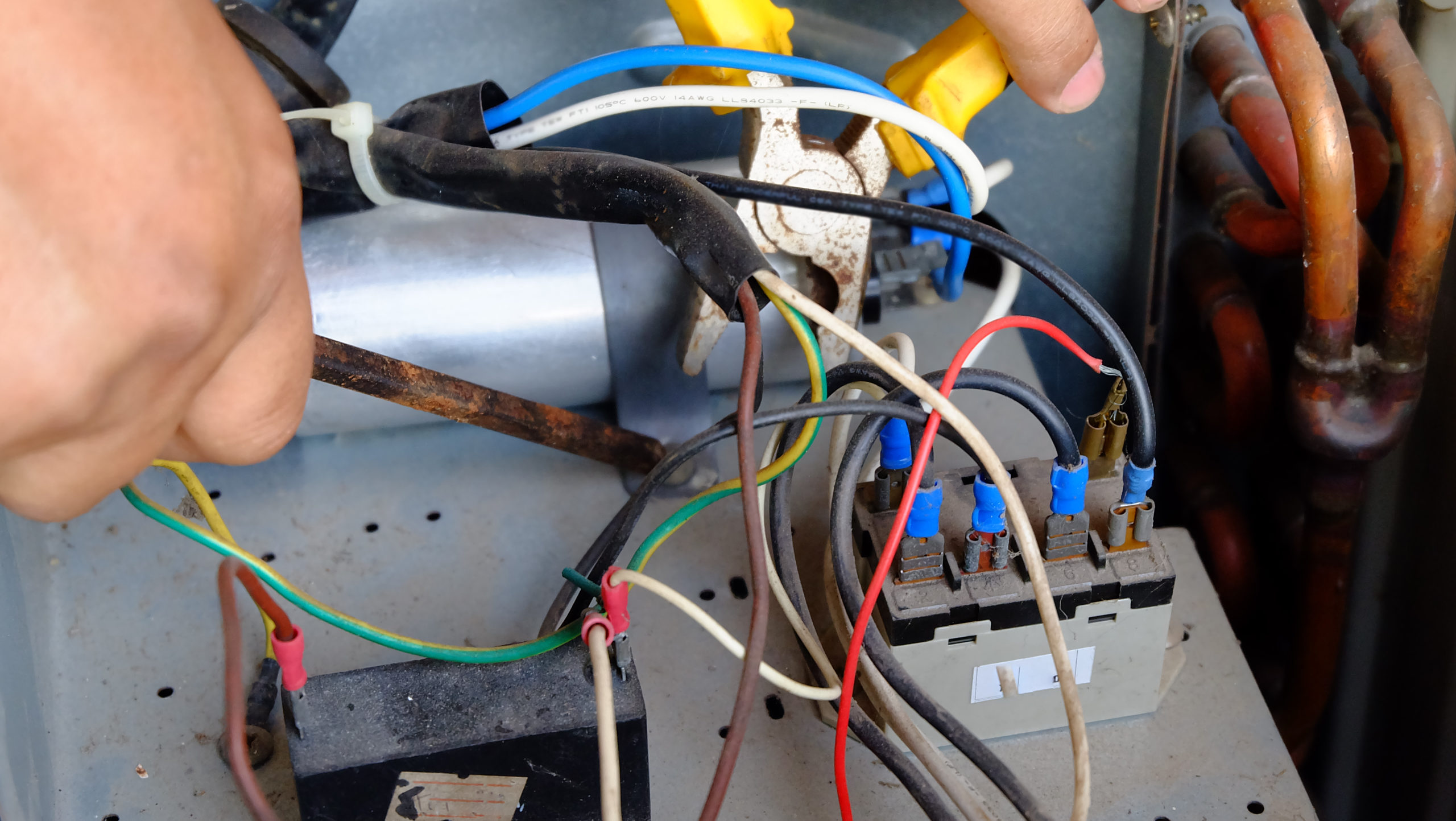
HVAC diagrams have an unfair reputation for being hard to understand. In fact, once you learn what each symbol in the schematics represents, you’ll be able to easily read the manufacturer’s diagrams, troubleshoot issues quickly and even create your own diagrams.
Representing System Components With Symbols
Understanding an HVAC diagram requires a thorough knowledge of symbols. The following are particularly important to remember.
Electrical Loads
An electrical load is anything that consumes a current draw and performs work in a circuit including motors, solenoids, lights and heaters.
Motors will have their own specific symbols denoting motor design and an abbreviation indicating its function (compressor, evaporator fan, condenser fan, indoor fan motor, etc). The symbol for a motor might reflect the motor’s design as well, and an abbreviation for its function in the system is usually included.


A solenoid is defined as a current flowing through a coil of wire, producing a magnetic field and causing an action in a relay or valve, for instance, the plunger in a solenoid valve. A contactor is similar, with current flowing through a coil and activating a switch.

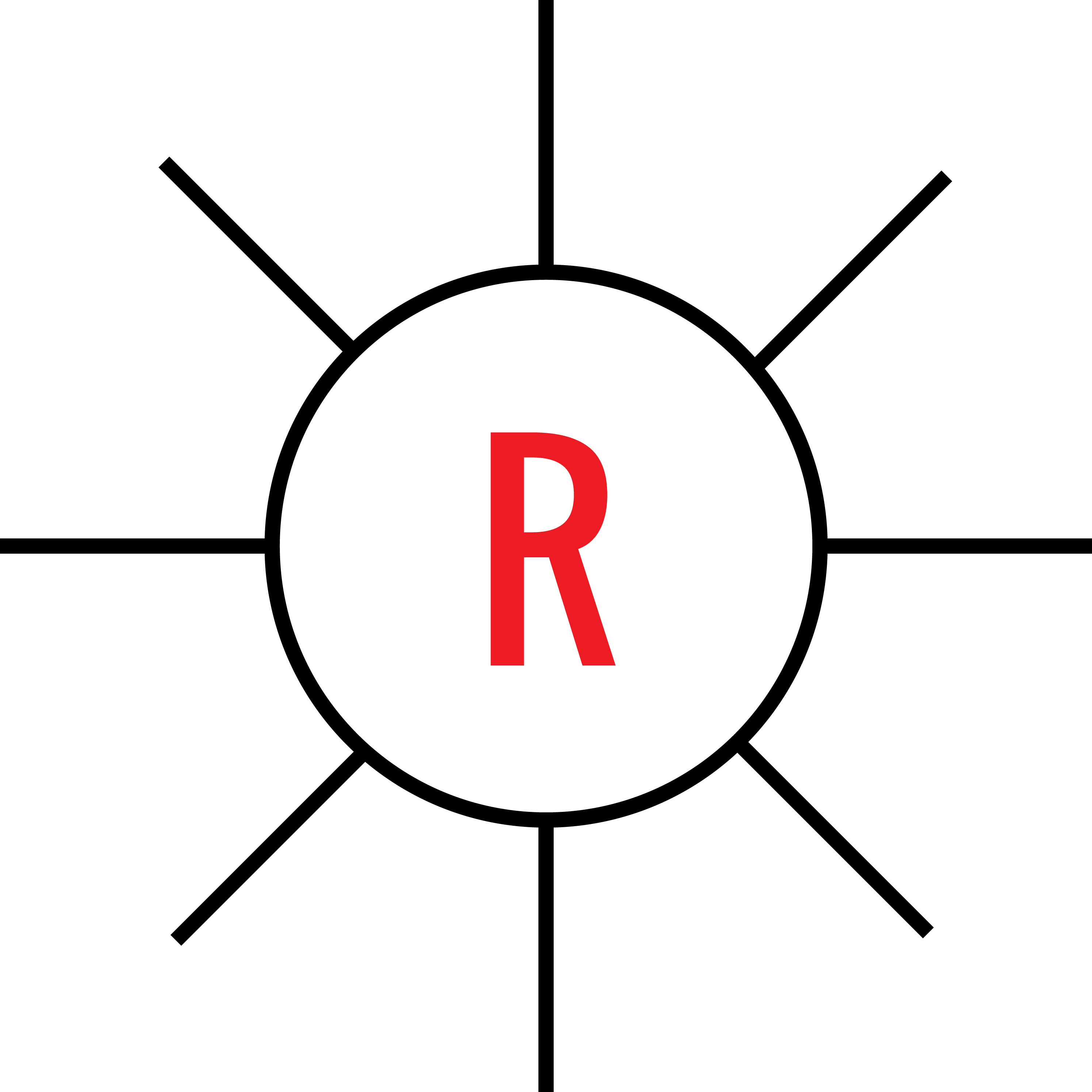
Signal lights are important indicators in HVAC controls, marking when a part of the system or a component is working. These signal lights will have a symbol like a cartoon drawing of the sun, with a letter designating the light’s color.
Electrical heaters convert electrical energy into heat. For example, the crankcase heater for a compressor prevents refrigerant from migrating back into the compressor and causing a flooded start.

Switches interrupt the voltage in a load and can be operated manually or electrically. Contacts refers to the conducting part of the switch, poles are the number of sets of contacts and throws are the number of closed contact positions for each pole. These symbols denote a single-pole/single-throw and double-pole/double-throw switch:


Understanding the Basics: Schematic and Pictorial Wiring Diagrams
In the field, a schematic (aka ladder diagram) gives you a roadmap for understanding how a system is designed and laid out –– making the process of diagnosing a problem much easier.
Why Is It Called A Ladder Diagram?
Think of a ladder’s two rails as being an electrical supply (hot and neutral) going into a system. The rungs of the ladder represent loads, such as motors, the compressor, switches, solenoids and other components that either interrupt or perform a function in the circuit.
You’ll find that different manufacturers use different styles for their diagrams, but some features are consistent, such as:
- Symbols for switches are standardized
- Operating controls such as relays and thermostats are usually depicted in the open position
- Safety controls (overloads, high pressure/low pressure, limit switches) are usually depicted in the closed position
- Relay contacts are depicted as if the relay coil is de-energized
Here’s a typical ladder diagram:
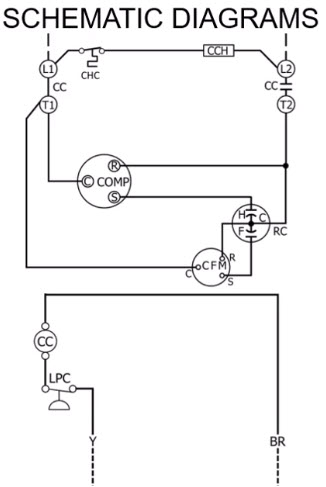
Some detailed wiring diagrams will show numbers on the left denoting the lines or circuits, with numbers on the right side indicating circuit lines with relays or switches. Underlined numbers on the right side will denote contacts that are normally closed.
Using the diagram like a map, will help you figure out:
- Where power is coming from
- Which switches control which loads
- How the switches are controlled
- The normal sequence of operation for the system
A typical factory diagram can be broken down into:
- Pictorial diagram
- Schematic diagrams for low voltage/high voltage
- Component codes
- Wiring information
- Wiring color codes
- Equipment description
- Any notes
Pictorial diagrams have the same information, but are laid out differently from ladder diagrams. Often, pictorial diagrams will show a dotted line to indicate where the wiring needs to go during installation. This is more for the benefit of installers, but can also be useful for HVAC techs during troubleshooting.
How To Utilize HVAC Diagrams In The Field
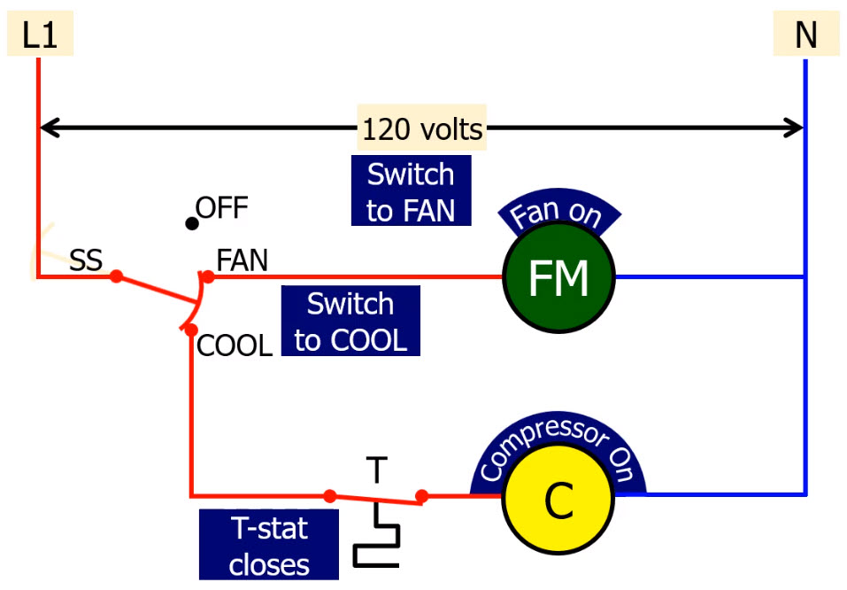
Being able to identify electrical symbols and understand how they fit into a system will help you, not only read a manufacturer’s HVAC diagram, but also create your own diagram for troubleshooting an issue. Common HVAC diagrams to familiarize yourself with include:
AC Unit
A diagram for an AC unit usually includes:
- Contactor
- Compressor
- Crankcase heater
- Low-pressure and high-pressure controls
- Condenser and indoor fan motors
- Ground connection
- Run capacitor
- Low voltage and Line voltage wiring
Heat Pump
A heat pump wiring diagram includes components such as:
- Contactor
- Compressor
- Crankcase heater
- Low-pressure controls
- Condenser and indoor fan motors
- Defrost control board
- Ground connection
- Run capacitor
- Solenoid for reversing valve
- Low voltage and line voltage wiring
By simply learning symbols for HVAC diagrams, you can begin to get a bigger picture of an entire unit, which makes diagnosing problems easier. To find out more about how to boost your skills and understanding of schematics and diagrams, check out the Interplay Learning Symbols and Wiring Diagrams course.

